Molding Defects
For below molding defects, there are design guidelines to reduce them.
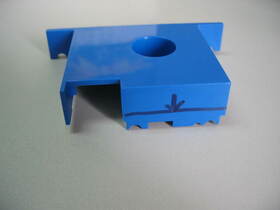
1. Burn Marks:
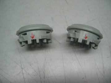
Burn marks may appear as black or dark discoloration when a material burns during the injection molding process.
Causes:-
@Overheating due to trapped air
@Excessive injection speed
@Excessive melt temperature.
Solutions:-
@Shortening the cycle time.
@ Lowering the temperature and/or slowing down the injection speed
@ Trapped air can be avoided by ensuring adequate gas vents and gate sizes .
@ Mold flow during mold design with inserts in advance of tool making might help.
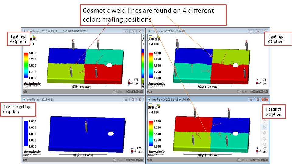
2. Gate location:
Every injection-molded part has at least one gate, and some have several gates.
The placement of the gate can help ensure the cavity fills properly, weld lines, air trapped, etc.., can be a deciding factor in the success of a part.
Best designed with the gate in a location at which the melt enters the thickest section of the cavity to a narrower region.
3. Insufficient Draft:
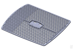
When a part is designed without appropriate draft, removal of plastic parts is essentially impossible. Even if it does, damages/scratches/deformation all on cosmetic/functional plastic parts.
It is a must to determine the surface finish / texture requirements prior to starting you part design. Surface textures also influence draft requirements. The more depth in a texture the more draft it requires.
4. Warpage/Deformation
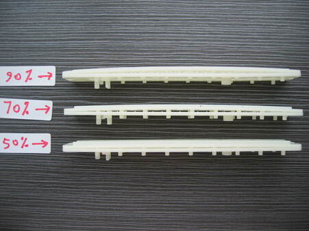
It is likely due to internal stress created during injection pressure.
Inherent part design is root cause :-
@ It can help to reduce using injection process by means of different % of holding pressure in relation to injecton pressure.
@ DFM report at start of tool making with mold flow can help to optimum by finding the best gate location (plastic material injection point).
@ Sometimes, a cooling jig will be in-cooperated immediately after molding for fixation to avoid further bending.
@ Worst case is to make a prototpe tool to verify its bending level and direction, it then machine another tool in verse direction, with play and try error, thus hoping to mold a straight part in final. Yet, it limits in application to mold parting surface.
@ some other means open for discussion ....
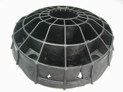
5. Air Traps
Bubbles have two primary causes: gas pockets or vacuum voids. Both of these are essentially air-flow related issues.
To differentiate between gas pockets or vacuum voids you can use a simple heat test. By using a hot air gun or small lighter, warm the area of the part that has the bubble until it begins to soften up. If the bubble expands, you've got a gas pocket. If the bubble collapses, it's a vacuum void.
Gas pockets are usually a result of
@ jetting which is a front flow issue. Solution: Venting with inserts
@ Another cause of bubbling may be as simple as moisture. Solution: Proper dry of material.
@Poor melt flow pattern (proved by short shot) is a major cause of bubbles. Solution: Change venting location.
@Incorrect barrel screws
* General-purpose screws with dimensions of 18:1 L/D or lower can be root causes for a bubble or blister.
* raise the backpressure to 1000 to 1500 psi melt pressure.
* pull a vacuum on the mold just before injection, so that air is pulled out.
Since airflow is the major source of the problem, a preventative routine maintenance plan to make sure all heated parts are venting properly will help keep bubbles away. Follow up with periodic machine maintenance and continuous random part inspection and you should keep running smoothly.
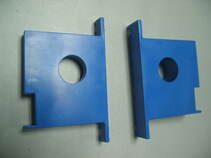
6. Discoloration:
Discoloration is a defect that shows a streak of coloring in the end product. It usually occurs in one of two cases:
Discoloration is a defect that shows a streak of coloring in the end product. It usually occurs in one of two cases:
- Not evenly mixed of the additive used for coloring material
- Impurities in the material during the molding process. It is imperative that an injection molder clean the injection molding machine prior to producing parts.
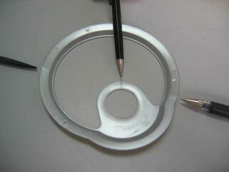
7. Weld Lines
It affects costmetic as well as easy breakage at those locations. Weld lines appear in a part where molten plastics of inadequate bonding.
Weld lines can be avoided by:
@ Increase temperature of the mold or molten plastic
@ Increase the injection speed
@ Change the design for the flow pattern with new gate location or modify inherent part design
@ Select a plastic with a lower melt temperature
@ We might use overflow-well to move it to outside of part, then trim the extra plastic well off, especially for strength consideration
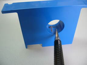
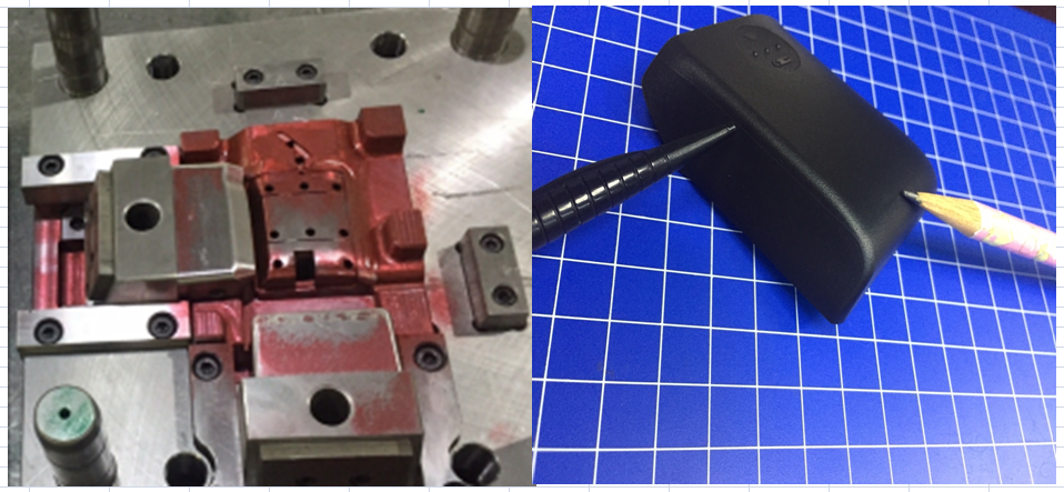
8. Flash:
Flash appears as a wafer-like extension on a finished part.
This defect occurs most often along the ejector pin and parting surface.
Flashes can be avoided by
@ not excessive injection speed or pressure,
@ not too high of mold temperature and not excessive barrel heat.
@ better mold design
@ tool maintenance.
@ modify inherent part design which induing weak shut off steel
|
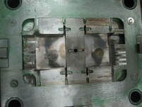
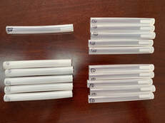
9. Roots from tooling craftsman
If a tool does not have a quality steel finish, flashes, demaged venting lines , then quality of parts will be definitely poor with high production scrap rate. Pls see below guidelines for keeping a good mold maintenance. https://www.injectionmoldingsupplier.com/mold-maintenance.html |
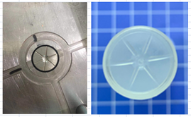
10. Roots from plastic material selection
Cosmetic of products, like warpage/deformation is sometimes not on tool design and highly demand of balancing in plastic injection points. It is rather due to selection of better high flow index materials, thus contributing less warpage/internal stress. .https://www.tsymolding.com/injection-tooling.html |
11. Flow Leader / Restrictor
A flow leader is a local increase in wall stock to promote plastic flow.
A flow restrictor is a local reduction in wall stock to inhibit flow.
Used correctly, flow leaders and restrictors can improve the quality of molded parts when conventional means cannot.
This reduction in the part’s packing variation, which leads to more uniform shrinkage, results in less warpage.
How should this flow leader be designed ? • @ Design at the press.
Steel is grinded off of the mold’s core side as it is in the injection machine during the mold trial.
@ Design by the moldmaker.
The mold is returned to the shop to be properly machined to specifications for the flow leader.
This approach may take a few modification to get the flow right.
@ Use simulation.
Designing flow leaders using simulation takes the guesswork out and does not require the moldmaker to go through multiple tuning with tirals.
